
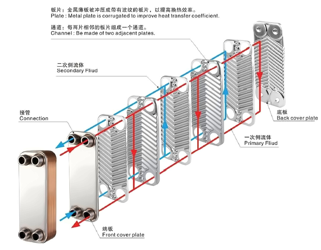
The core function of the CDU is to efficiently transfer heat from the secondary side to the primary side using a brazed plate heat exchanger. Structurally, it's straightforward: dozens of stainless steel plates, approximately 03mm thick with embossed patterns, are stacked together. Adjacent plates form two separate flow channels—one for the primary-side medium and one for the secondary-side medium. There are no gaskets or bolts; the entire core is pressed together and then fused into a single unit in a vacuum furnace.
Dense flow channels limit maximum flow rates. The chevron corrugation design forces fluid to change direction continuously, even at low flow, disrupting laminar flow and enhancing turbulence to boost heat transfer coefficients—all while maintaining a compact footprint. In CDU cabinets, this component is typically the largest and heaviest.
Material: 31 6L plates, copper brazing
The plate isAISI 316LThe low-carbon version of 316 with molybdenum offers excellent pitting corrosion resistance and weldability. Our immersion liquid cooling system uses ethylene glycol or propylene glycol on the primary side, and synthetic oil or fluorinated fluid on the secondary side. This plate heat exchanger is designed for long-term operation with these two types of coolants. The 6L plate works perfectly on both sides, and the copper brazing material is fully compatible with them. Plate thickness selection:0.3mmThin the wall to reduce thermal resistance, provided it remains within pressure limits.
The braze material is copper. In vacuum brazing, the assembled plate stack is placed in a vacuum furnace and heated above 1084°C to melt the copper foil. Capillary action draws the molten copper into every contact point, resulting in a single solid unit once cooled. This construction offers high temperature and pressure resistance, eliminating aging and leakage issues common with rubber gaskets.
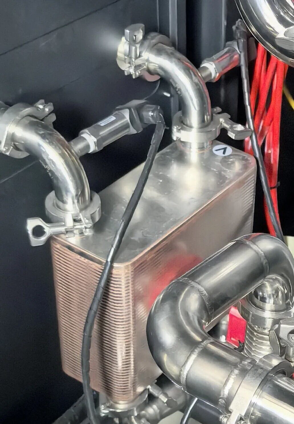
Why is the fouling factor so low?
The value provided by this case project is0.00002 m²·K/kWPeople seeing this number for the first time often think it's too small.
The "small" value is conditional. This plate heat exchanger features closed-loop circuits on both sides: the primary side uses an alcohol-based solution, while the secondary side employs synthetic oil or fluorinated fluid. With no evaporation or concentration occurring and the media exhibiting virtually no tendency to foul, conditions for fouling are essentially nonexistent. This value serves as the basis for our sizing calculations. Field data from actual projects confirms that significant degradation in heat transfer performance has not been observed.
Ratio: 1:1
Customers often ask if we keep a margin. For our 80kW CDU, the ratio between plate heat exchange capacity and CDU design cooling capacity is 1:1.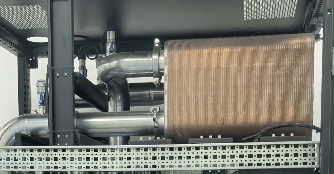
This means that under rated conditions, with flow rates and inlet/outlet temperatures specified on both sides, the required heat transfer area is calculated using the log mean temperature difference (LMTD) and overall heat transfer coefficient. The selected plate heat exchanger provides exactly the capacity needed for the design heat dissipation, so no additional safety margin is necessary.
Secondly, the secondary-side medium significantly impacts calculations. Synthetic oil has high viscosity and flow resistance, requiring data-driven modeling for heat transfer coefficients and pressure drop; fluorinated fluids have low specific heat, necessitating higher flow rates for the same heat exchange load. Changing the medium requires recalculating the overall heat transfer coefficient—the plate configuration cannot be directly reused. 1:1 is not a one-size-fits-all solution; under different operating conditions or tighter approach temperature requirements, the ratio must be recalculated. Therefore, the plate heat exchanger in a CDU is less "selected" and more calculated alongside the entire system.
Maintenance is actually simple.
In a closed system, heat exchanger maintenance mainly involves two things. First,Filter1. Install filters with the appropriate mesh size for both primary and secondary inlets based on the medium used. Crucially, ensure no particles enter the flow channels, as this can cause local blockages. 2. CheckDataIf the temperature difference approaches significantly higher than factory test values, it indicates an issue with the medium or a blockage. To address this, we install pressure sensors before and after the filter to monitor differential pressure in real time. Our algorithms analyze this data to detect issues, trigger alerts, and prompt timely maintenance.